Faulty Fuel Gauge

Renault & Alpine General Discussion

Moderators: eastlmark, BIG_MVS, phildini, Test Moderator, Alpineandy

no avatar
User

108002917

Rank

Non Member

Posts

73

Joined

Mon Dec 27, 2004 4:10 pm

Location

Pontypridd South Wales


Has thanked: 0 time
Been thanked: 0 time

Postby 108002917 » Thu Feb 19, 2009 9:34 am

John/Stephen,

I have driven the car this morning and unfortunately no change to the flashing display, although as I have mentioned previously, the other features on the computer are behaving as normal.

The one thing that I did notice though, was the colour of the needles/dial? I know that I mentioned that they were red previously, but after looking at them closely they appear to be a definite Orange in colour?? How many colours are there?
I know that I have another speedo unit that Dave G supplied me before, and the colour of the needles/dials on that one is a much lighter Orange colour..... which I was led to believe was the later version?

So did the very early cars have a definite Red needle/dial combination? If that is the case, then it may explain why I have the sensor control unit on the car?

I forgot my wiring diagram this morning, so I will attach the other info for you tonight and hopefully if get a chance some details of the control unit as well.

Cheers
User avatar
User

JohnC

Rank

Non Member

Posts

2120

Joined

Sun Dec 02, 2007 6:19 pm

Location

Jersey C.I.


Has thanked: 15 times
Been thanked: 83 times

Postby JohnC » Thu Feb 19, 2009 10:25 am

Jeff,
Interesting...It looks as if yours should have a TSU (tank SENDER unit), if your needles are indeed Orange, now we have established that, the pt.No. of the SENSOR should confirm what system is in your Alp. But try and get the TSU pt.No as well, it is on the unit. If all is confirmed I have the cct for this system, including the relay.
I will let Stephen confirm the colours, and other questions you have relating to the instruments, as I got my info from his postings when he had both units for sale some time ago :wink:
1990 GTA Atmo, 2003 Jaguar X type 2.5SE Auto, 2018 Kia Picanto GT-Line-S 1.25
no avatar
User

108002917

Rank

Non Member

Posts

73

Joined

Mon Dec 27, 2004 4:10 pm

Location

Pontypridd South Wales


Has thanked: 0 time
Been thanked: 0 time

Postby 108002917 » Thu Feb 19, 2009 9:45 pm

John,
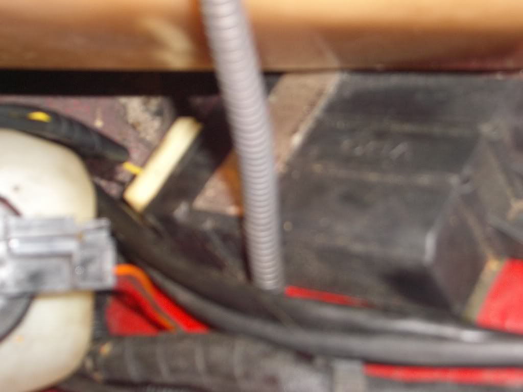
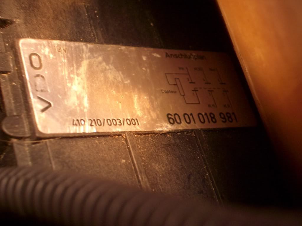
I have managed to remove the boot liner and get you some pics of the fuel sensor control unit. It is a VDO unit part number 186 810 10 09.
ImageImage
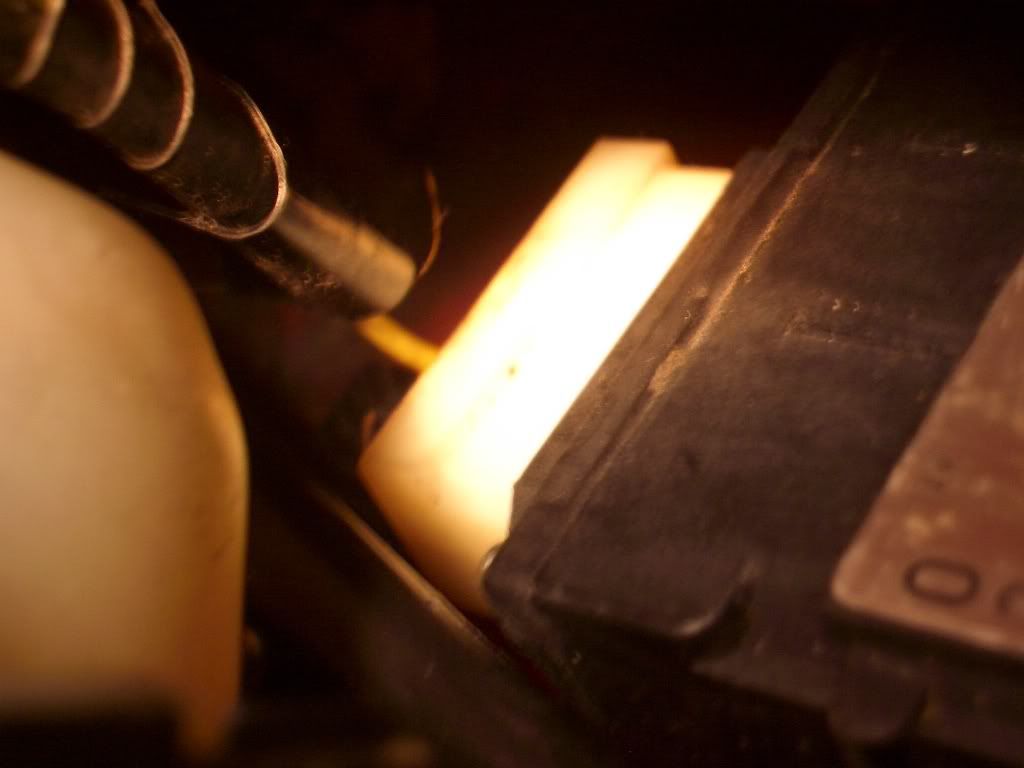
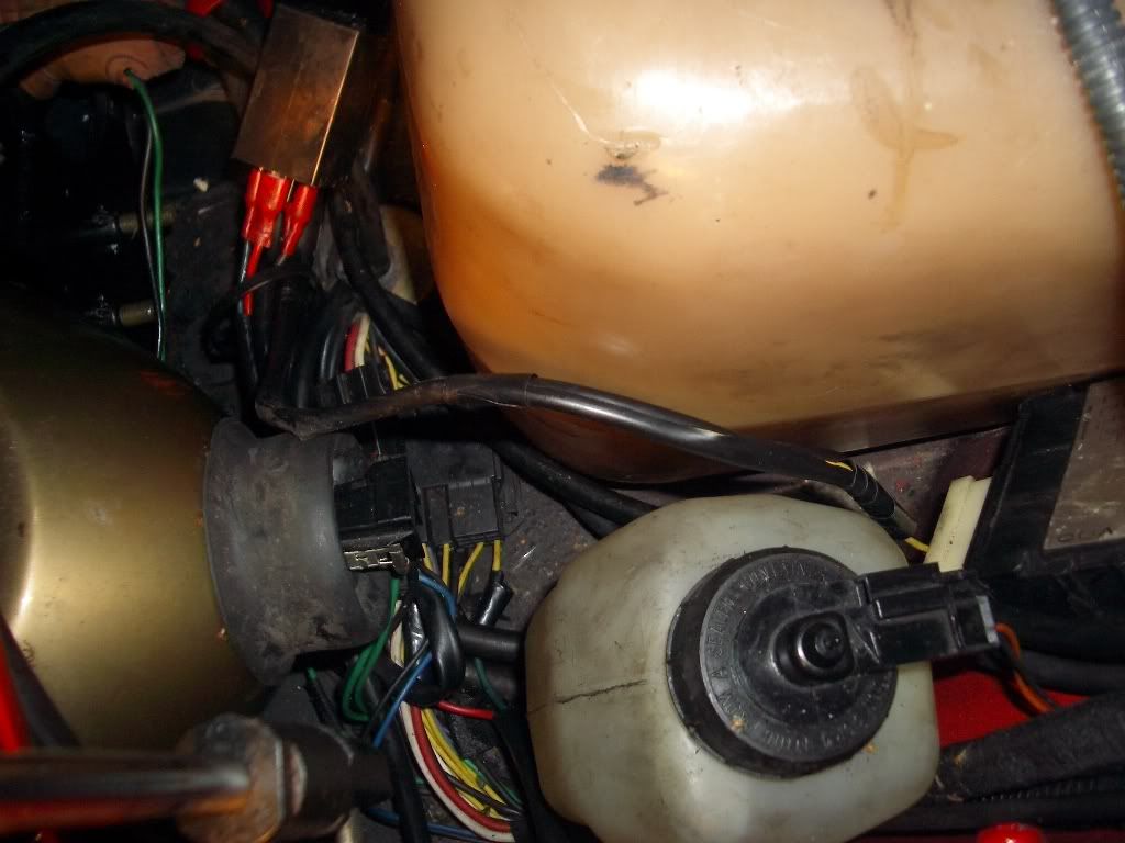
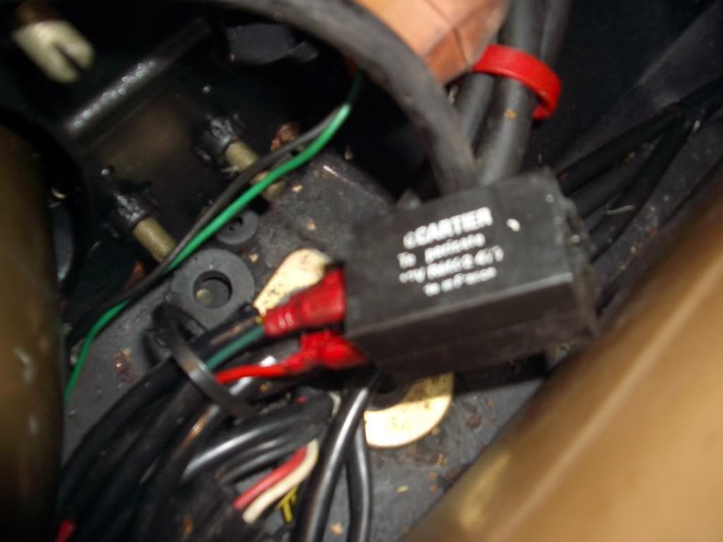
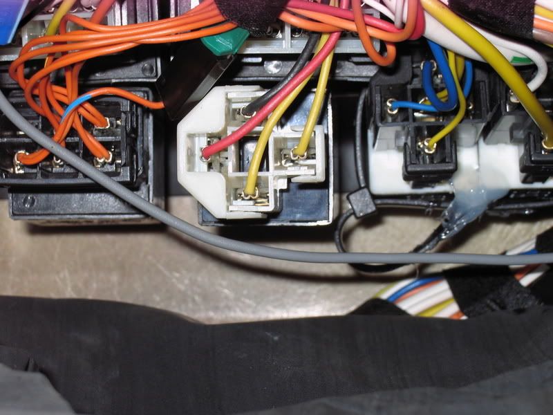
Strangely though there is a yellow wire tapped in to the socket plug which is feeding a relay ( see pics).
ImageImageImage
The socket plug has 3 orange combination wires and one red one, the yellow is coming from the red wire.I am not sure what the relay is connected to, but I dont think that it is an original fitment although it is professionally fitted. I think that it may relate to the Air con system which was fitted from new?

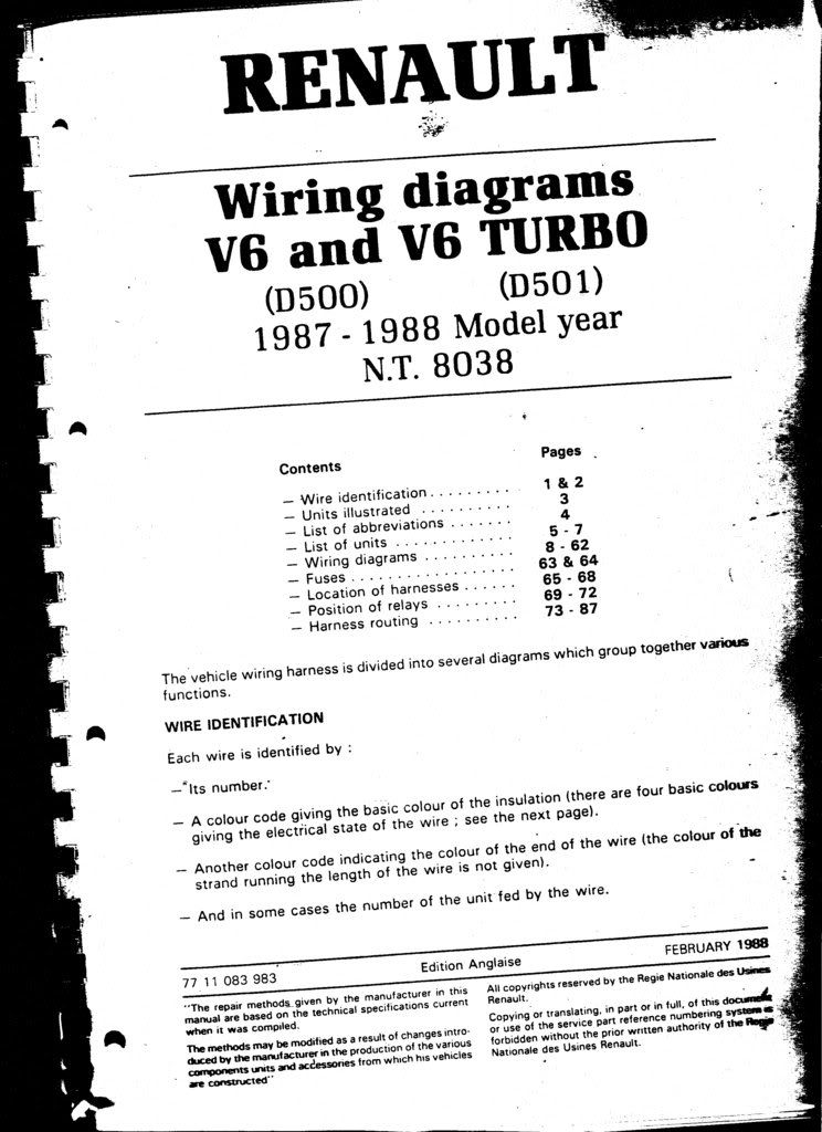
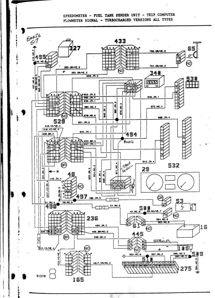
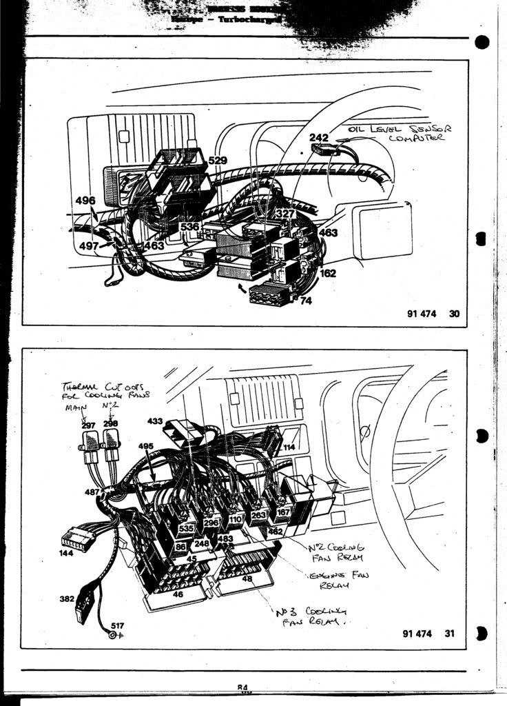
I am also attaching the wiring and relay diagrams and I have included the manual cover as well so that you can see which one it is.
If possible I would appreciate if you can upload a the wiring diagram you mentioned so that I can try and fathom out the relationship of the relay that Martin mentioned? Hopefully the fault will prove to be the relay?
ImageImageImage
User avatar
User

JohnC

Rank

Non Member

Posts

2120

Joined

Sun Dec 02, 2007 6:19 pm

Location

Jersey C.I.


Has thanked: 15 times
Been thanked: 83 times

Postby JohnC » Thu Feb 19, 2009 11:32 pm

Jeff, that unit is defintely the TSU. but your cct diag is clearly not for your Alp in this area. In fact it is the same as the `86 one for the fuel gauge cct. This afternoon I did hi-light the gauge cct from my manual with the TSU, and the "Fuel Gauge Sender Unit Computer Timer Relay" (FGSUCTR from now on :lol: ) in order to work out what the relay was for. I concluded that it delays the 12v to the TSU for a few seconds, in order to allow the computer to stabilize before the pulses start coming in. It is possible that the Fuel Gauge was not stable before the Timer Relay was fitted.

Image

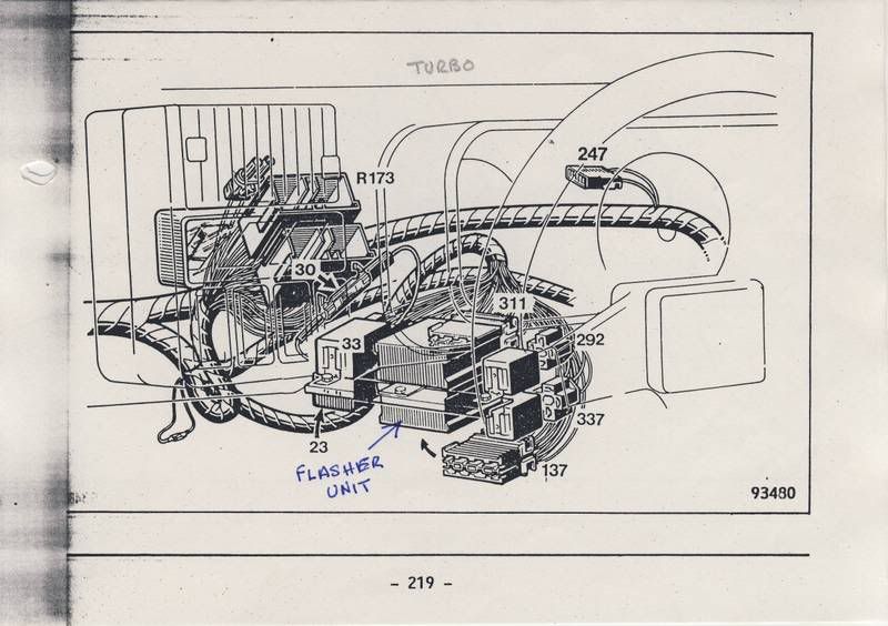
Your diags do not show the location of the relay, which is 33 in the cct, but as you can see it is connected via a yellow lead to the TSU. Is it possible to trace the yellow wire to a relay? as it might have been fitted close to the TSU if my theory is right. The connections to the TSU are:-

1...Blank...........2...Blank
3...Computer.....4...Black Earth
5...Red 12v........6...Yellow...this one should come from the Relay
7...Sensor.........8...Sensor

The relay should have 4 wires going to it:- 1...Yellow from ign sw. 2...Black Earth 3...Yellow. to the TSU 5...Red, 12v from Battery. The middle pin, if it has one is blank.
I am coming round to Martins thought that if the Relay does not function, it might cause your problem, as the other functions (MPG ect.) are OK.
If you look at the pic that Martin posted showing the relays, I have identified all of the relays from crossreferencing them in the manual, and I think the FTSUCT relay, is the Black one on the far right, sorry Martin, but the one you thought it might be has too many pins.
I am not too sure where you will find this relay as your manual does not show it, but it might be in the same place as shown below in my manual.

Image
Item 33 lower Pic behind the fuse box.

In the first instance what I would do would be to check the volages on the TSU, ie:- Ign off....12v on the Red lead, pin 5...there should be no volts on Yellow lead, pin6...leave meter on pin 6, switch on ign, and 12v should appear after a few seconds, if my theory is correct. But what ever happens, 12v must appear on pin 6, when ign is switched on, (4 string_Jon please note :wink:)
I cant think of anything else at the moment, but when you get around to it, let us know how you get on.

Cheers

John
Last edited by JohnC on Fri Feb 20, 2009 3:52 pm, edited 1 time in total.
1990 GTA Atmo, 2003 Jaguar X type 2.5SE Auto, 2018 Kia Picanto GT-Line-S 1.25
User avatar
User

JohnC

Rank

Non Member

Posts

2120

Joined

Sun Dec 02, 2007 6:19 pm

Location

Jersey C.I.


Has thanked: 15 times
Been thanked: 83 times

Postby JohnC » Thu Feb 19, 2009 11:43 pm

I have just looked back at your pics and the Carter relay in the third pic on the right, looks very similar to the one in Martins pic, on the far right, which is the one I think is the FTSUCTR,... see if there is a wire going from the TSU pin 6,... to pin 1 of the relay.
1990 GTA Atmo, 2003 Jaguar X type 2.5SE Auto, 2018 Kia Picanto GT-Line-S 1.25
no avatar
User

108002917

Rank

Non Member

Posts

73

Joined

Mon Dec 27, 2004 4:10 pm

Location

Pontypridd South Wales


Has thanked: 0 time
Been thanked: 0 time

Postby 108002917 » Fri Feb 20, 2009 8:52 am

John,

That is brilliant!! The diagram at least gives me a chance to understand the logic of the circuit and hopefully I will be able to track down where the current is dropping off.
Thanks for taking so much time to illustrate the circuit, your help is really appreciated.

There are a couple of things though that do not seem consistent? The wiring showing for the TSU is showing 6 wires? When I looked at the wiring on mine, there was only 4 wires and they were also different colours? Mine were mainly orange with one red.
Also the relay that Martin mentioned was showing 6 terminals, whereby the one in the diagram is only showing 4 connections, so there is still something that is different, but I guess that this is marvels of Renault.

I won't have time this weekend, but I will certainly look for the relay first and see what happens.

With respect to the other relay, I noticed that it was a French make relay which is consisitent with it being there from new, but unless the spade connectors had been changed at some point, they were definitely not original connectors. I will try and track it to make sure that it is not part of the circuit?

Thanks again,

Jeff
User avatar
User

JohnC

Rank

Non Member

Posts

2120

Joined

Sun Dec 02, 2007 6:19 pm

Location

Jersey C.I.


Has thanked: 15 times
Been thanked: 83 times

Postby JohnC » Fri Feb 20, 2009 11:34 am

There are a couple of things though that do not seem consistent? The wiring showing for the TSU is showing 6 wires? When I looked at the wiring on mine, there was only 4 wires.


Jeff, When you get around to it, you are going to have to investigate further, your part No. is the same as in the Parts Book, and they do require all 6 pins to be connected. There is a diag on the box of your TSU showing the 6 connections. Can you unbolt the TSU from the wing so as to get a clearer look at it?
As a matter of interest this is what they look like inside.

Image

You will see the 6 connections on the right of the board which come up and through the box cover to the connector. The diag of the pins is on the left of the pic.

Also the relay that Martin mentioned was showing 6 terminals, whereby the one in the diagram is only showing 4 connections,


I thought I covered that before by saying that I thought the one Martin said was the one, had too many pins, in fairness he did say that he only thought it might be the one. I think that the Black one on the far right of his pic is the one.
Hope this clears up any inconsistencies.

John
1990 GTA Atmo, 2003 Jaguar X type 2.5SE Auto, 2018 Kia Picanto GT-Line-S 1.25
no avatar
User

108002917

Rank

Non Member

Posts

73

Joined

Mon Dec 27, 2004 4:10 pm

Location

Pontypridd South Wales


Has thanked: 0 time
Been thanked: 0 time

Postby 108002917 » Fri Feb 20, 2009 11:44 am

John,

I can see now why Renault want £170 for it!!

With respect to your comments about the relay, I was coming to the same conclusion. The relay on the very right of the rail appears to be exactly the same relay as that is in my picture? Also after looking at the wiring diagram more closely, it does have a yellow wire feed coming from the TSU going to the relay, so it could very well be the same one? It should be easy to check if the feed is getting to the relay, or if the relay is not working?

Because this relay/TSU set up is not showing in my wiring manual, do you think that it is possible that Renault installed a temporary revision to the wiring system until they relased the later wiring system for the '89 cars where they made a permanent change?
Cheers
User avatar
User

JohnC

Rank

Non Member

Posts

2120

Joined

Sun Dec 02, 2007 6:19 pm

Location

Jersey C.I.


Has thanked: 15 times
Been thanked: 83 times

Postby JohnC » Fri Feb 20, 2009 12:10 pm


Also after looking at the wiring diagram more closely, it does have a yellow wire feed coming from the TSU going to the relay, so it
could very well be the same one? It should be easy to check if the feed is getting to the relay, or if the relay is not working?


Hi Jeff.
Yes, it should be easy to check with your meter. If you dont get your 12v on the Yellow wire when you switch on the ign, let me know
and I have an idea how to trick it and to prove the relay.
Just checking back on your quote, the feed does not come FROM the TSU, but comes from the Relay TO the TSU, a minor detail but important :wink:

Because this relay/TSU set up is not showing in my wiring manual, do you think that it is possible that Renault installed a temporary
revision to the wiring system until they relased the later wiring system for the '89 cars where they made a permanent change?


Yes, somthing like that possibly. It is difficult to know exactally what happened, but my feeling is that the new sensor and TSU were fitted,
and it was only after production that it might have been shown to be unstable, that the extra relay in your cars case, was fitted either in
the factory, or after sale, in order to procure a fix. However that is pure spectulation :wink:

Good Luck

John
Last edited by JohnC on Fri Feb 20, 2009 4:09 pm, edited 2 times in total.
1990 GTA Atmo, 2003 Jaguar X type 2.5SE Auto, 2018 Kia Picanto GT-Line-S 1.25
User avatar
User

JohnC

Rank

Non Member

Posts

2120

Joined

Sun Dec 02, 2007 6:19 pm

Location

Jersey C.I.


Has thanked: 15 times
Been thanked: 83 times

Postby JohnC » Fri Feb 20, 2009 3:39 pm

OK....so curiousity got the better of me this afternoon, and I wanted to prove my theory......guess what.......Wrong :evil:
I found the relay, see below middle of pic, behind the fuse box and easily identified it, clipped on the meter,
and it clicked on at the same time as I turned on the ignition. :shock:
But it now appears that the timer activates when you switch off for just over 30secs holding the voltage up.
Why it should need to do that, I do not know, as the TSU has power on it all the time while the battery is connected.
I then disconnected the relay (as if it had failed) and the fuel reading went up to 18.7 gals.
I reconnected the relay, switched on and the reading stayed at 18.7, and I had to do a full computer reset
in order to get my original 14.4 gal reading.
You can hear the relay click in and out, which is useful for trouble shooting.

Image

I was hoping to get the relay out but it does seem like a big job to get to the fixing bolt, not something I want to do for fun!!!
Anyway for what it is worth, there it is. I hope it helps someone at some time or another :wink:
1990 GTA Atmo, 2003 Jaguar X type 2.5SE Auto, 2018 Kia Picanto GT-Line-S 1.25
no avatar
User

108002917

Rank

Non Member

Posts

73

Joined

Mon Dec 27, 2004 4:10 pm

Location

Pontypridd South Wales


Has thanked: 0 time
Been thanked: 0 time

Postby 108002917 » Fri Feb 20, 2009 4:32 pm

John,

I wished you lived closer?? Just to clarify the postion of your relay, was it just behind the original fuse box and relay areas, adn did you get to it by swinging it down as you previously suggested.

I will obviously try the relay in the underbonnet area first, but in case I need to find out if it exists in the same area, the information will be usefull.

I don't want to push my luck, you have been more than helpfull already, but have you ever gone to the same levels to find the speedometer faults? I have tried various things over the last 2 years without any real lasting success. I had 10 years of disbelieving the speedo problems and at least 2 years knowing that they are real!! I have tried a lot of the suggestions posted and have posted some myself, but I have never been convinced that the route cause has been found? I am sure that it is a common fault and is probably the same fault that everyone has, it's just finding out where it is? My expectation is that it is either a component of the PCB or a bad earth somewhere, but finding and proving it is the problem?

In case you have, please let me know.
Thanks again.
User avatar
User

JohnC

Rank

Non Member

Posts

2120

Joined

Sun Dec 02, 2007 6:19 pm

Location

Jersey C.I.


Has thanked: 15 times
Been thanked: 83 times

Postby JohnC » Fri Feb 20, 2009 7:26 pm


Just to clarify the postion of your relay, was it just behind the original fuse box
and relay areas, adn did you get to it by swinging it down as you previously suggested.


Yes, it took me 2 - 3 mins to get to it, 3 screws on the cover, 2 on the front rail, then swing down the assembly.

but have you ever gone to the same levels to find the speedometer faults?


Yes. I have had my fair share of faults, but you will have to be very specific on the faults you have or have had.
If it is intermittent, that is usually the connectors, or failing that, dry or cracked cct board solder joints.
I have also had a transistor failure causing the needle to jump slightly on switch on. But I did a through overhaul
with a fine tipped soldering iron, and I hav`nt had a prob since. But great care must be taken with doing that.
Once your gauge is working if you have specific faults with your speedo, we can have a go at that if you wish.
1990 GTA Atmo, 2003 Jaguar X type 2.5SE Auto, 2018 Kia Picanto GT-Line-S 1.25
no avatar
User

rupert

Rank

Non Member

Posts

1323

Joined

Mon Apr 19, 2004 7:39 pm

Location

Plymouth, Devon


Has thanked: 2 times
Been thanked: 9 times

Postby rupert » Fri Feb 20, 2009 7:35 pm

When I had a similar problem, ie the display flashing and saying it had 18.7gals, this amount reduced as you drove, suggesting that the electrics were all fine.
So rather than checking all the 'solid state' bits, I followed the diagnosis in the manual and realised the tank level sensor was not working, removed it and found the internal springy/wire thing that runs to the float was busted. Well worth checking this, by just removing the tank send unit.
User avatar
User

JohnC

Rank

Non Member

Posts

2120

Joined

Sun Dec 02, 2007 6:19 pm

Location

Jersey C.I.


Has thanked: 15 times
Been thanked: 83 times

Postby JohnC » Fri Feb 20, 2009 9:48 pm

When I had a similar problem, ie the display flashing and saying it had 18.7gals,

Well worth checking this, by just removing the tank send unit.


Hi Rupert
You were lucky to go to the faulty sensor first, as according to the manual ANY fault in the fuel gauge cct, and the flow meter cct in fact,
will cause the display to flash.
I note that yours with a faulty sensor showed 18.7,... mine shows 18.7 with the TSU timer relay removed. But I take your point, if the relay
proves to be OK, which has yet to be checked, we may have to check the resistance across the sensor, as you suggest.
Thanks for your comment anyway, it all helps :wink:
John
1990 GTA Atmo, 2003 Jaguar X type 2.5SE Auto, 2018 Kia Picanto GT-Line-S 1.25
no avatar
User

108002917

Rank

Non Member

Posts

73

Joined

Mon Dec 27, 2004 4:10 pm

Location

Pontypridd South Wales


Has thanked: 0 time
Been thanked: 0 time

Postby 108002917 » Mon Feb 23, 2009 2:42 pm

Hi John,

I have carried out some further checks today and I am almost certain that it is the TSU that has failed.
The TSU must have been a modification that Renault done before they released the permanent fix The relay that we discussed is certainly the relay going to the TSU and appears to be working OK. I have checked the various feeds to and from the relay and everything is working as it should. The relay also has a timer in it which keeps the 12v supply feed for an additional 1-2mins before switching off?

I have removed the TSU, it wasn't bolted on as you suggested, but stuck on with double sided tape(another reason to suggest it was modified) and confirmed that there are 6 wires feeding into the TSU.

I have checked continuity from the relay(yellow wire), permanant feed (red), the earth(black) and the 2 orange wires going to the tank sensor. The only one I haven't checked is the output wire going to the display?

The tank sensor seems to be working OK... No resistance when full and .82 ohms when empty. It is currently registering .62 so seems to be OK.

With everything connected, I have checked the voltage going to the tank sensor and it seems to be a continuous .48 volts whether the ignition is switched on or not. I assume that this must be through the permanent 12v feed going to the TSU.
I have also checked the voltage on the output side of the TSU ( going to the display) and it is showing zero? This is the same regardless of whether the ign is on or off.

I have held off checking the continuity of the connection to the gauge because of this reason.

I am certain that there is nothing else I can check other than fitting another TSU unit, but I would like your comments first in case there is something else that I should have checked?

So it looks like the worst case scenario - does anyone have a TSU hanging around anywhere?

Martin, Have you got one from the time that you stripped your car?

Please let me know.

Cheers,

Jeff
PreviousNext


  • Advertisement

Who is online

Users browsing this forum: No registered users and 153 guests

Powered by phpBB ® | Renault' and 'Alpine' are trademarks of Renault S.A.S. or its subsidiaries and are used with kind permission of Renault France