Need Alignment Help!

A place to showcase your pride and joy

Moderators: eastlmark, BIG_MVS, Test Moderator

no avatar
User

dallarax19

Rank

Non Member

Posts

99

Joined

Tue Oct 30, 2012 1:44 am


Has thanked: 0 time
Been thanked: 1 time

Need Alignment Help!

Postby dallarax19 » Mon Sep 26, 2016 1:42 am

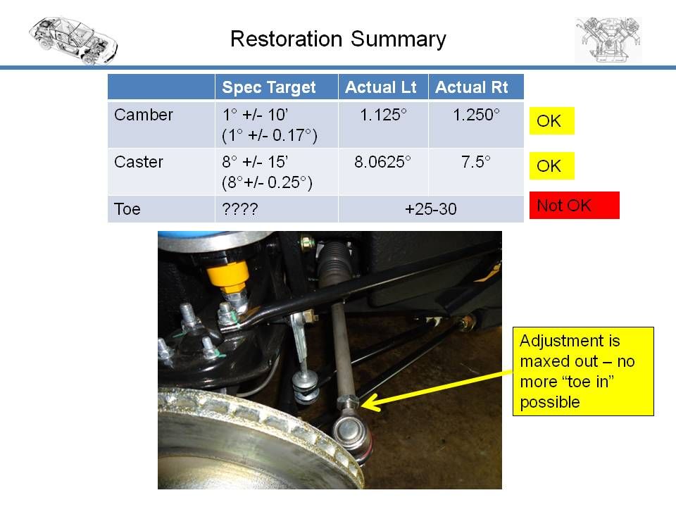
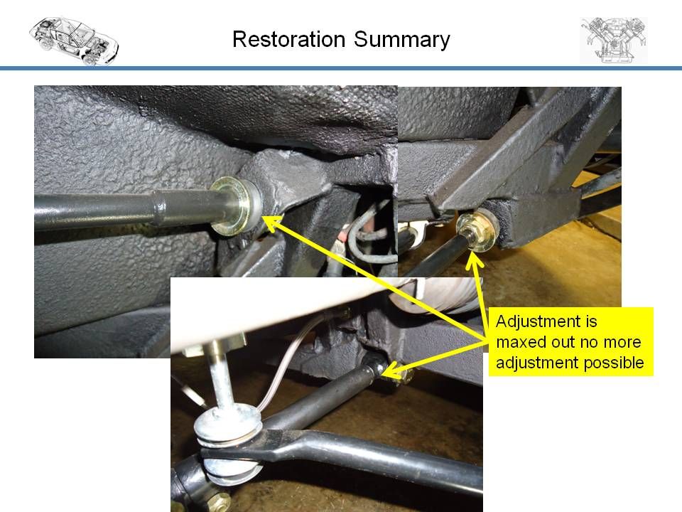
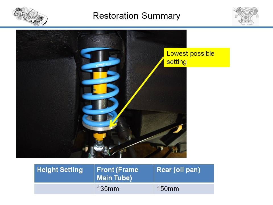
I am finalizing my suspension settings before I drive the car and I am finding the front suspension alignment is not going well. There is something wrong however I cannot yet identify what. I am hoping someone can help based on their experience. Specifically I cannot set the toe in the front wheels and almost all alignment adjustments are at the end of their range. The other attributes I have dialed in pretty close but to do so I am at the end of their adjustment range. A key point is I have the Spax/Eibach adjustable coilover set from Simon. Let me know your recommendations.

Image
Image
Image

I would appreciate the help.

Brian
User avatar
User

johnb

Rank

Non Member

Posts

858

Joined

Wed Sep 13, 2006 6:57 pm

Location

Cheshire


Has thanked: 13 times
Been thanked: 25 times

Re: Need Alignment Help!

Postby johnb » Mon Sep 26, 2016 3:50 pm

Can’t help you much Brian other than to make a few observations.

- I think you have a copy of the Alpine MDR in which section G shows the front suspension settings. My copy (page G-5b) shows the camber setting as -20’ to -35’ for 1978 models onwards. Your Phase 2 car might have slightly different values.

- The MDR caster value is the same as you’ve stated.

- For Toe the MDR states 2 – 3 mm (total across both wheels) pince upto 1977 and 2 – 3 mm ouverture (total across both wheels) from 1978. I understand ‘pince’ to mean toe-in and ‘ouverture’ to mean toe-out. On my car the toe-out was set as the book a couple of years ago and there’s plenty of thread at the ball joint ends. From your photo there looks as if there’s some thread visible, difficult to see, but maybe not a lot. You say your actual toe is +25-30, presumably mm, that’s a lot and it can’t be reduced? Can’t offer any explanation for that unless something is bent or the new track rods are longer than the old ones. Presumably you’ve compared new and old. Did the old track rods have any exposed thread implying that they could be adjusted and do you know what toe-in/toe-out you had before dismantling, for comparison? I don’t know what effect your spring adjustments might have on toe geometry.

- Regarding your second photo and the top left of the three showing the upper tie-rod. You say adjustment is maxed out. In the MDR there’s a note at the bottom of page G-10b and also mentioned on page G-22b, that in cars from serial number 45946 onwards, the upper tie-rod is not adjustable. It’s just fastened in position. I think that this would apply to your car. On page G-23b are drawings of the earlier adjustable type (No.1) and the later non-adjustable type (No.2). From your photo yours looks like the later rod and it looks as if it’s assembled correctly with single steel and single rubber washer between the rod end the chassis. Presumably the same two washers on the other side of the chassis hole.

- The top right of the three photos showing the lower, adjustable tie-rod that adjusts the caster setting. Difficult to see from the photo but it looks as if it’s assembled correctly with the two different thickness locknuts, steel washer and rubber washer at the chassis. Presumably the same on the other side of the chassis hole. On my car there’s about 10 mm of exposed screw thread, on each rod, where your arrow is pointing.

- The bottom photo of the three, showing the lower suspension arm, looks a bit different to the arrangement on my car, see photo. At the chassis end, where your arrow points, and where the camber adjustment is made, there isn’t a clamp but there is at the wheel end. On my car the wheel end of the tube is welded to the end piece that attaches to the hub. Difficult to see but in your photo it almost looks as if there’s adjustment at the wheel end also with the clamp to prevent relative movement. Could be a misinterpretation with the clamp just being out of position. Anyway, on my car there’s very little exposed screw thread showing at the inner end with the camber set correctly.

- I can’t comment about the spring/damper arrangement. I used the original springs with new Mecaparts standard dampers.
You do not have the required permissions to view the files attached to this post.
1970 A110V85 and 1980 A310V6.
no avatar
User

dallarax19

Rank

Non Member

Posts

99

Joined

Tue Oct 30, 2012 1:44 am


Has thanked: 0 time
Been thanked: 1 time

Re: Need Alignment Help!

Postby dallarax19 » Mon Sep 26, 2016 5:37 pm

Hey John

Thank you for the prompt response. I appreciate the comments, I had written the post after a long day of working on the front end of the car and missed mentioning some key points.

1) The year of the car is 1982 A310
2) The camber is -1deg (negative one - top of tire leans inward toward the centerline of the chassis) not 1deg as stated in my pic
3) The toe is in mm and measured toe out (wide at the front end of the car)
4) Most of the parts are new
a) Upper control arms with ball joints
b) Lower control arm ball joints
c) Lower control arm bushing (inner pivot)
d) All radius rod bushings
e) Tie rods and ball joints
f) Shock absorbers and springs

From the start point the wheels were -3deg camber and by turning in the lower control arm bushing to the end of adjustment I got the wheels to just over the -1.0 target. The lower radius rod was adjusted to the caster setting, the upper was fixed and is not really adjustable. The tie rod ends were turned in all the way to the point of using up all the adjustment. As I understand it I am only 5mm lower than the standard chassis height.

Everything indicates to me I have an incorrect part and I am suspecting the upper control arm is too short. The height difference should not be enough to alter the geometry to the extent of the problems I see.

I am using these gauges to set the alignment - they are what I use on my track car
http://www.racerpartswholesale.com/prod ... ber_Gauges
http://www.racerpartswholesale.com/prod ... ser_Plates

I think to start, the best action is to compare the upper control arm length to a known good part. The next is to compare the length of the tie rod end relative to the steering rack clamp. There is something fundamentally wrong for this much of a mismatch. I should not have to adjust the lower control arm and tie rod bushing all the way to the end of the adjustment allowance and still not quite meet the spec. I would also like to know the chassis height other people are set at using the SPAX/Eibach adjustable shock absorbers.


John, concerning your points, the radius rods all look great and the chassis does not show any impact damage. I have no adjustment on the upper radius rod and the lower is adjusted about 10mm of exposed thread( as you mentioned). On the lower control arm the clamp is there but loose and at the wheel end to get it out of the way to screw in the the inner bushing pivot. There is no adjustment on the outer ball joint. The fact that your car has limited thread exposed at that bushing is GOLD! At least that shows some consistency. I have had trouble getting consistent parts and on more than one occasion got mismatches. For example the upper control arms looked the same when I got them but upon closer look one had a different ball joint (taller taper), I got one of type A and type B. The vendor sent a set of ball joints for which I had to retrofit the arm - not real happy about that one. I just recently ordered the struts for the rear decklid and one was from one manufacturer and one from another. When I went to put them in the car one fit fine and the other did not. Turns out the lug at the base of the strut was different and did not clear mounting bracket. The supplier sent a new lug to screw on and that fixed the problem. This make me a bit leery about the parts.

I am also not really happy about the adjustable coilover as well. I have no idea of the spring rate but the rear seems OK however the front springs are 50-75mm too tall. There really isn't any height adjustment. The spring diameter does not look like a standard racing spring so I will have to find (and pay for again) a spring that works.

Let me know if you think of anything.

Regards,

Brian
no avatar
User

dallarax19

Rank

Non Member

Posts

99

Joined

Tue Oct 30, 2012 1:44 am


Has thanked: 0 time
Been thanked: 1 time

Re: Need Alignment Help!

Postby dallarax19 » Tue Sep 27, 2016 2:26 am

I have not yet found a good photo reference but I am wondering if I have the lower control arm misassembled. Should the ball joint be on top of the arm?

Image
User avatar
User

clee

Rank

Non Member

Posts

10431

Joined

Fri May 28, 2004 11:58 am

Location

Derbyshire


Has thanked: 54 times
Been thanked: 104 times

Re: Need Alignment Help!

Postby clee » Tue Sep 27, 2016 7:24 am

Will check when I get in work but I think you have a plate missing .Just stripped one down and there was a plate attached as well as the balljoint .Just need to check fitment .
User avatar
User

clee

Rank

Non Member

Posts

10431

Joined

Fri May 28, 2004 11:58 am

Location

Derbyshire


Has thanked: 54 times
Been thanked: 104 times

Re: Need Alignment Help!

Postby clee » Tue Sep 27, 2016 7:28 am

Quick google for a pic ....
Image
User avatar
User

johnb

Rank

Non Member

Posts

858

Joined

Wed Sep 13, 2006 6:57 pm

Location

Cheshire


Has thanked: 13 times
Been thanked: 25 times

Re: Need Alignment Help!

Postby johnb » Tue Sep 27, 2016 8:52 am

clee wrote:Quick google for a pic ....

Image


I think that one is a Phase 1 Lee. The yellow machine should be like Brian's car.

Brian,
You could have a point about the ball joint position. On my car it is on top of the lower suspension arm. There are differences between the PHase 1 and 2 lower suspension arms and the ball joints are different. My parts books shows the Phase 1 parts relationship with the ball joint on top but where it shows the Phase 2 ball joint it doesn't show it in relation to the lower suspension arm. Lee should be able to tell you from the yellow machine.

Something else I notice is that in your photo the lower, diagonal tie-rod is attached to the underside of the plate on the suspension arm. On my car and in the parts book it's positioned on the top side of the plate. Again my parts book doesn't show the full assembly for the Phase 2 so, for your car, I don't know which is correct.

Lee mentioned another plate. On mine this is attached on top of the ball joint and diagonal tie-rod.

Attached is a photo of the same side of my car and a photo of the lower suspension arm assembly. These might help.

A daft question but, didn't you take photos or notes before dismantling?
You do not have the required permissions to view the files attached to this post.
1970 A110V85 and 1980 A310V6.
User avatar
User

simontaylor

Rank

Non Member

Posts

5602

Joined

Thu Apr 15, 2004 12:33 pm

Location

Fleet, Hampshire


Has thanked: 44 times
Been thanked: 56 times

Re: Need Alignment Help!

Postby simontaylor » Tue Sep 27, 2016 9:53 am

This is the sort of thread that could be listed in the "reasons to join the club" section.
Outstanding International support from fellow club members and professionals in the trade too.
1986 : '86 GTA v6 BW-EFR turbo, with Adaptronic ECU
Firsts at
2007 : Gurston Down & RAOC Champion
2008 : Rushmoor & Eelmoor & ACSMC Hillclimb class Champion
2009 : Longcross & Eelmoor
2010 : Crystal Palace & Eelmoor
2016 : Rushmoor & 5th O/A
User avatar
User

johnb

Rank

Non Member

Posts

858

Joined

Wed Sep 13, 2006 6:57 pm

Location

Cheshire


Has thanked: 13 times
Been thanked: 25 times

Re: Need Alignment Help!

Postby johnb » Tue Sep 27, 2016 10:22 am

Brian,

Attached is a page from the I.S. section at the end of the MDR showing the Phase 2 front suspension.

If you enlarge it you can see that the way that you've assembled the ball joint appears to be correct. In the top view there does appear to be a small plate below and to the right of the ball joint.

Also attached are two photos from a French internet site showing a Phase 2 restoration. The assembly photo appears to verify the drawing in the MDR and that yours is correct. The other photo of the parts shows what appear to be the small plates next to the suspension arms.
You do not have the required permissions to view the files attached to this post.
1970 A110V85 and 1980 A310V6.
no avatar
User

dallarax19

Rank

Non Member

Posts

99

Joined

Tue Oct 30, 2012 1:44 am


Has thanked: 0 time
Been thanked: 1 time

Re: Need Alignment Help!

Postby dallarax19 » Tue Sep 27, 2016 11:39 am

Certainly no daft questions being asked, I have missed something basic and need help. I do have extensive before and after photos and the car has been reassembled exactly the same. I have the computer out next to the car and went through the entire procedure again last night. With that said there are no guarantees it was in proper order in the "before" state The reinforcement plates are a good example, there weren't any on the car. I will fabricate a set up. I have researched the illustration many times and don't always know if the pics apply to me or not. Another example is another car owner told me my radiator support brackets were not base car; it seemed odd to me because they look just like the ones illustrated in the manual (and the same in the photo below). I also see in photo the tie rod end is also at the extreme end of its adjustment - turned all the way in like my car (another clue).

Given the parts are all the correct lengths (I will post photos on this topic later) the only thing left is ride height. I would think the car would have to be drastically lowered or lifted to solve a 25-30mm toe out problem. I have not given that much of a look yet.

Got it Simon, I never thought of joining the club because I am not a local guy. I will check it out. The help everyone has provided has be excellent so you have a good point.
User avatar
User

clee

Rank

Non Member

Posts

10431

Joined

Fri May 28, 2004 11:58 am

Location

Derbyshire


Has thanked: 54 times
Been thanked: 104 times

Re: Need Alignment Help!

Postby clee » Tue Sep 27, 2016 12:47 pm

This is assembly on the Big Banana 310
WP_20160927_008.jpg


I'm sure its something simple ...it could still look like this so chin up
WP_20160927_004.jpg
You do not have the required permissions to view the files attached to this post.
User avatar
User

johnb

Rank

Non Member

Posts

858

Joined

Wed Sep 13, 2006 6:57 pm

Location

Cheshire


Has thanked: 13 times
Been thanked: 25 times

Re: Need Alignment Help!

Postby johnb » Tue Sep 27, 2016 2:54 pm

dallarax19 wrote:4) Most of the parts are new
a) Upper control arms with ball joints
b) Lower control arm ball joints
c) Lower control arm bushing (inner pivot)
d) All radius rod bushings
e) Tie rods and ball joints
f) Shock absorbers and springs

Just to clarify terminology:-
Where you say ‘Upper control arms with ball joints’ I presume you’re refering to the pressed steel arms that attach to the chassis and the top of the hub via the ball joint?
Similarly for the lower control arm I presume you mean the tubular arm from the chassis to the lower end of the hub via the ball joint.
For the ‘radius rods’ I presume you mean the diagonal upper and lower rods between the front of the chassis and the top and bottom of the upper and lower ‘control arms’.
For the ‘tie rods and ball joints’ I presume you mean the steering track rods from the steering rack to the hub arm via the ball joints.
Apologies for needing the clarification but just wanted to be sure as I’m familiar with different terms.
dallarax19 wrote:Everything indicates to me I have an incorrect part and I am suspecting the upper control arm is too short. The height difference should not be enough to alter the geometry to the extent of the problems I see.

This is why I was asking, so you mean the pressed steel arms? I’d be surprised if they were too short but if they’re remanufactured parts then, who knows. Where were they from?
dallarax19 wrote:I think to start, the best action is to compare the upper control arm length to a known good part.

Presumably you’ve compared them with the original ones that were on the car?
dallarax19 wrote:The next is to compare the length of the tie rod end relative to the steering rack clamp.

Not sure where you’ll be making this measurement but, for what it’s worth, attached is a photo of the ‘tie rods’ before they were fitted with dimensions I’ve taken today (nearside) as currently assembled and toe set correctly.
Looking at what the trade sell, Mecaparts only show one item for both Phase 1 & 2, GBS show two part numbers but the photo for each is the same, Simon Auto show two part numbers (111065 & 111066) but don’t say what differences there are. Possibly some difference in the ball joints.
You do not have the required permissions to view the files attached to this post.
1970 A110V85 and 1980 A310V6.
no avatar
User

dallarax19

Rank

Non Member

Posts

99

Joined

Tue Oct 30, 2012 1:44 am


Has thanked: 0 time
Been thanked: 1 time

Re: Need Alignment Help!

Postby dallarax19 » Tue Sep 27, 2016 5:25 pm

Hey John,

How do you have or find so many key photos??? I was looking at the parts suppliers last night to verify if there were differences and saw the same. They appear to have only one length. The photo is key! I will answer the questions first

1) YES Upper control arm = stamped part
2) YES Lower control arm = tubular arm
3) YES Radius rod = diagonal rods,
4) YES Tie rod = steering track rods
5) All parts from Simon
6) I compared the parts but never made a photo comparison to fall back on and they were replaced over a year ago and my memory fades a little more each day ;)

The measurement I took was from the end of the tie rod tube, just as you did, and the centerline of the ball on the ball joint. I believe it too was 230mm (I have it written in my log book at home and will have to check it)

I questioned the parts because I have had a bit of mix and match when I received the bits. The control arms had the same part number (I have a photo of that) but the ball stud tapers were different between the two arms. They may be fine but the fact they were not matching stays in the back of my mind as a concern. My next action is to look at the ground height and verify all is correct. Huge thanks again for the follow up.
User avatar
User

johnb

Rank

Non Member

Posts

858

Joined

Wed Sep 13, 2006 6:57 pm

Location

Cheshire


Has thanked: 13 times
Been thanked: 25 times

Re: Need Alignment Help!

Postby johnb » Tue Sep 27, 2016 7:01 pm

dallarax19 wrote:
How do you have or find so many key photos???


Quite simple really, probably similar to my attitude to what's in the garage. If something might be useful in the future I'll keep it, just in case. Over the years many of these things have been put into good use.
My A310 restoration took 3 years and during that time I found things on the internet relating to the A310 that might be useful and just bookmarked them on the computer. I hadn't owned an A310 previously so there was a lot to learn, as you will have found. Those two French site photos on this thread are an example.

dallarax19 wrote:I questioned the parts because I have had a bit of mix and match when I received the bits. The control arms had the same part number (I have a photo of that) but the ball stud tapers were different between the two arms. They may be fine but the fact they were not matching stays in the back of my mind as a concern.


Not very good quality/stock control then. You say they corrected the error so, hopefully, they should be OK. As I said previously I'd be surprised that anything would be wrong with the arm itself because I can't really imagine that they'd be a re-manufactured part. I could be wrong but I can't envisage that it would be economical to design and make the press tooling necessary to make the parts. The arm is very similar, and may be the same, as the one used on the Renault 12. If it is the same perhaps they have access to N.O.S. which they refurbish or have access to the press tools.
1970 A110V85 and 1980 A310V6.
no avatar
User

dallarax19

Rank

Non Member

Posts

99

Joined

Tue Oct 30, 2012 1:44 am


Has thanked: 0 time
Been thanked: 1 time

Re: Need Alignment Help!

Postby dallarax19 » Wed Sep 28, 2016 1:56 am

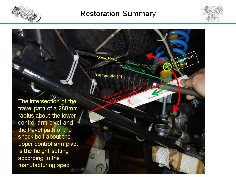
OK, I think I made some headway. The FAR guys brought up a standard "jig" that sets the relationship of the shock bolt head to the lower control arm pivot bolt head. The key dimension was reported as 280mm. So I just did some quick measurements and a basic kinematic swing study and the indication is my suspension is not compressed enough. See below:
Image

It appears my front springs are too tall. This is a first for me. Normally a coilover kit lowers the car so much it is difficult to dial out the toe in. So it is not conclusive but it makes sense to the issue I am having. I will see what the recommendation is from Simon.

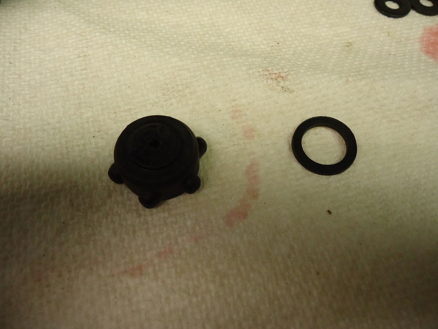
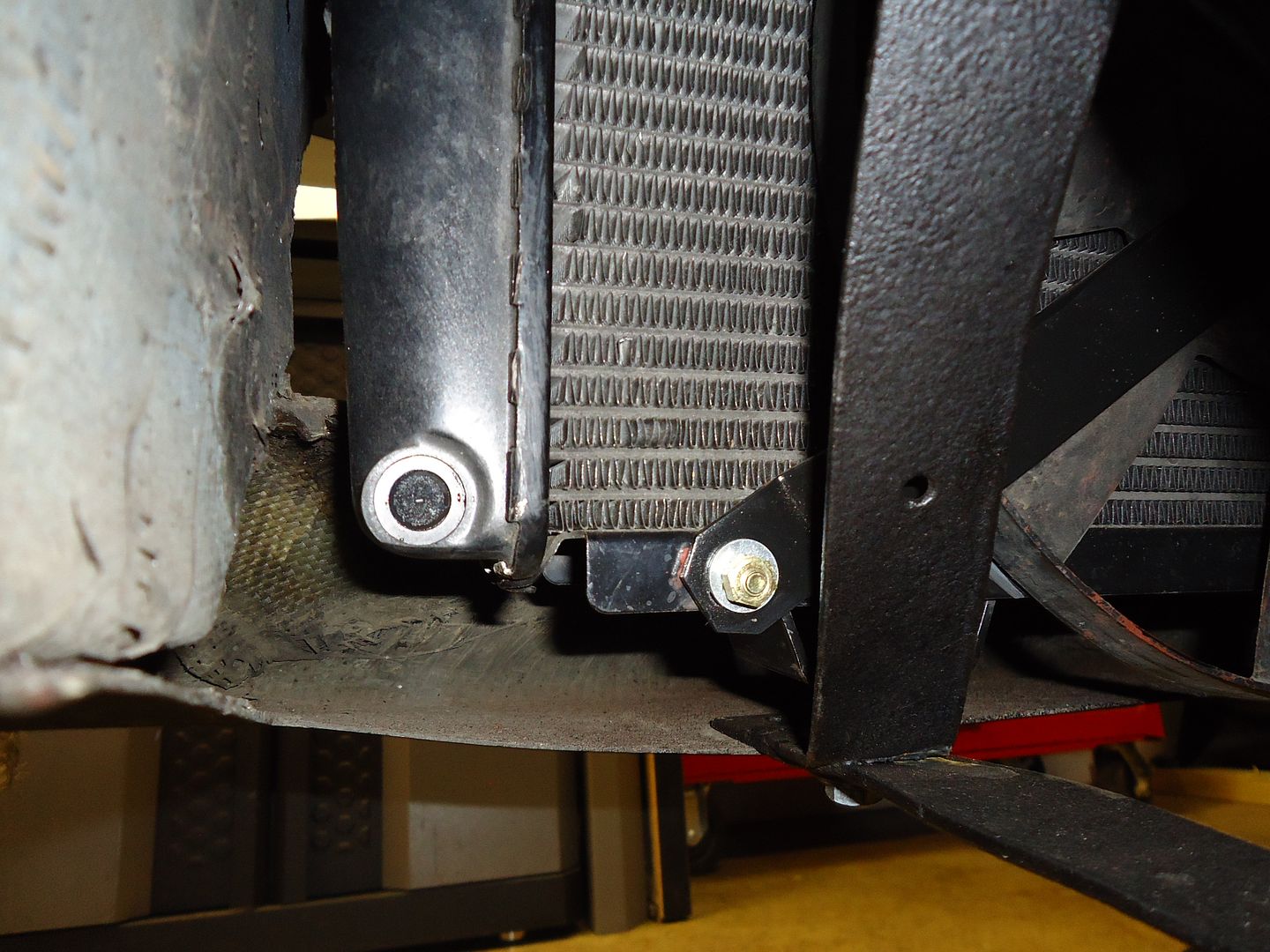
The car is still bringing me to my knees - ARGH! After 5 years of restoration I finally drove it around the block twice and found a little drizzle from the radiator after sitting overnight in my garage. It turns out the lower bleed screw fractured - what next?
Image
Image

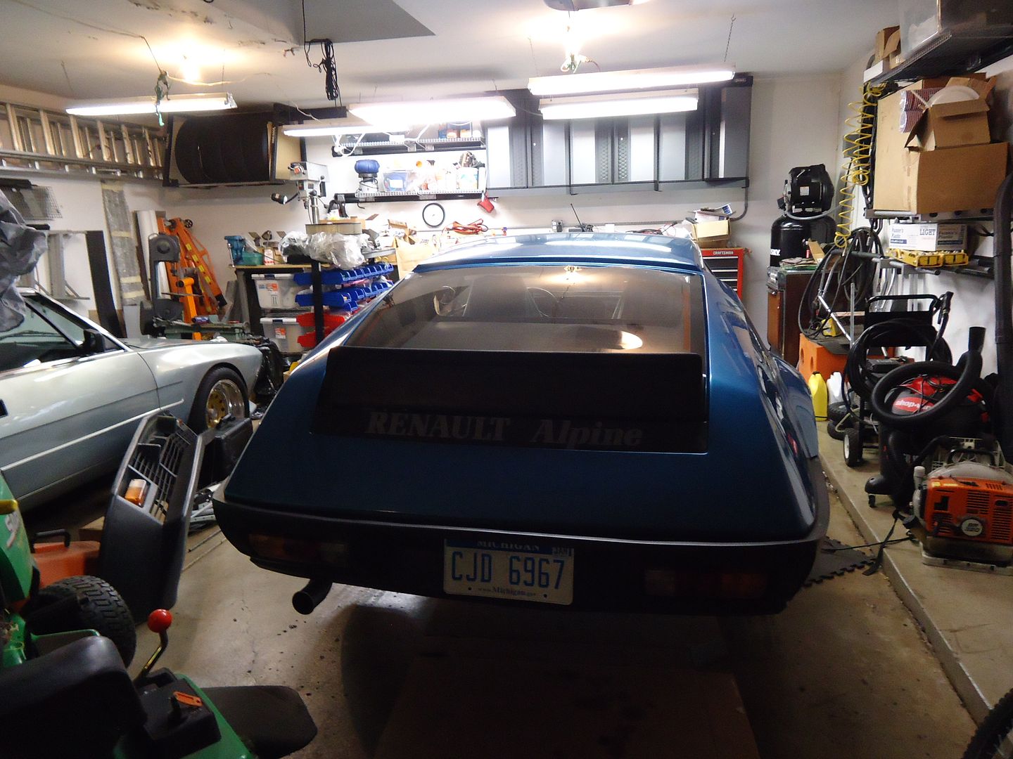
The picture of defeat...................back up on jackstands :thinking
Image
Next


  • Advertisement

Who is online

Users browsing this forum: No registered users and 35 guests

Powered by phpBB ® | Renault' and 'Alpine' are trademarks of Renault S.A.S. or its subsidiaries and are used with kind permission of Renault France